Rob's CNC Machine
My latest creation is a CNC(Computer Number Control) Machine. A CNC machine is a cutting machine(mill) driven by a computer and can
make 2D and 3D shapes in a variety of substances -- wood, metal, plastic, etc. I was reading about a device called a Makerbot which
makes shapes out of extruded plastic and sits on your desktop. It is also frightfully expensive. So while looking at
cool machines like that, I came across www.buildyourcnc.com.
This fantastic website shows you how to build a CNC machine as cheaply or expensively as you wish. I was hooked and
jumped right in. I worked on this alot and it took me two months to get it done. While I had run it to conduct tests and
to calibrate it, I ran it officially for the first time on Super Bowl Sunday 2011.
All told, the machine cost me $1,250 so far and I am quite pleased with it. It is accurate to 1/1000th of an inch, probably
even finer, but thats all I shall claim. Software is available for the machine via opensource or commercial outlets. I downloaded
Ubuntu Lucid Lynx(Linux) & EMC2(controller software) for no charge and got the machine running with a minimum of fuss. I hope to
make some really nice wood carvings and furniture with it.
I was so engrossed in building the machine that I forgot to take the pictures of the work being done. So there will be gaps
in the process.

Prepping the cabinet frame


|
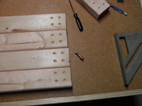
I started with straight, fresh, pine 2x3's from the hardware store. After laying out the design and cutting the pieces to length, I used
a jig to mark the locations of the wood screws. I then beveled each location to recess the head of the screw and then drilled the screw hole.
After this prep work was done, I sanded the pieces and treated them with linseed oil. Other pieces of the frame that were not being exposed
were not treated.
|
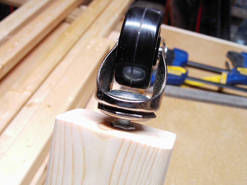
Roll around base


|
I used a spade bit to make a hole in the bottom of legs of the
frame. Into this hole, I forced a nut using a carriage bolt as a driver. The round head is good for tapping with a hammer. If you have
the bolt extend through the nut when forcing it into the wood, it leaves a round mark in the wood showing you where to drill the deeper
hole. Then, the nut is glued into the socket and an adjustable wheel is threaded into the end of the leg.
|
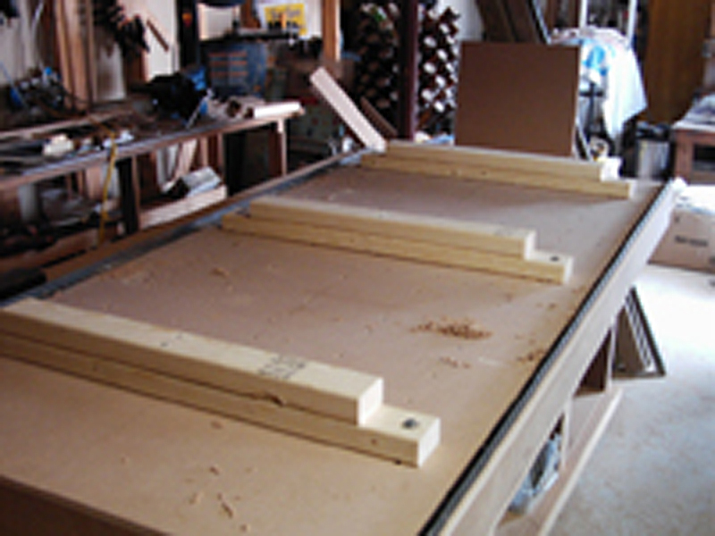
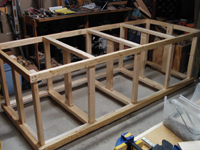
Cabinet assembly stage 1


|


|
The cabinet was constructed using a method known as pocket holes. Using a special jig, holes are drilled at an angle and then screws are
inserted into the holes to hold things together. It makes a strong joint and does not split the wood. In between the cabinet struts, I
added crossmembers to screw the interior panels to and also added crossbraces at the top and bottom of each section of cabinet. I used
inexpensive eucalyptus hardboard as interior walls. Exterior walls and doors will be added later after the need to work inside the
cabinet is no longer necessary.
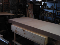
A sheet of 3/4 inch particle board was used as the cabinet work surface. I first bolted it to the cabinet using beveled screw holes
and exterior wood screws(great product). I then checked the cabinet for being level as that is quite important for a CNC machine. As
I suspected, it needed to be shimmed in the middle to bring the surface up to level.
|
Building the torsion box


|
A torsion box is a work surface that is built to be perfectly flat and so rigid that it will not flex at all. I had constructed one
previously for my wood working and I used it to build the CNC torsion box. I had decided on a 3ft by 6ft surface for the CNC. I trimmed
2x4 1/2 inch thick MDF sheets to 2x3. I laid these side by side and marked off a grid on the surface. I made sure grid lines lined up
with the seams. I then located and affixed 4 foot long strips of MDF along grid lines so they spanned all three panels providing some
overall stability. I then cut and glued the rest of the pieces to make the box grid. The seams were supported along their entire length
by the box pieces. Finally I glued an identical three panels to the top of the box, weighted it down heavily and let it sit overnight.
I got one sturdy, very heavy torsion box.
|
Prepping the torsion box


|
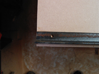
I chose V-groove bearings on angle iron rails as my tracking mechanism. I bought a bunch of cheap angle iron at the hardware store and
cut it to length. I then measured and drilled holes. Because of the way it is handled at the store, the iron was not straight. I made
spacer pieces to insure the rails were held parallel to each other and the torsion box, and then marked and drilled the mounting holes.
After running the edges across my belt sander to bevel the bearing edge and to remove crud, I glued and screwed the rails to the torsion
box. I then added layered 2x3 pieces of wood to make a raised stand for the box. I then centered the box on the table and aligned
with an end of the cabinet and screwed it into place.
|
Gantry Sides


|


|
Finally, onto building the CNC! The first thing you construct is the gantry.
I started by creating the side supports. After cutting out and dressing the gantry sides, I marked and drilled mounting holes. This
was an important step and I was undecided where to put things for quite awhile. I diagrammed it several times. The bearings need to fit
quite snugly on the rails so they roll smoothly with no free play. I cut elongated slots in the bottom mounting holes to allow for
adjustment. As the wood has some flex in it, I added a piece of strap iron, glued and screwed to the side to add rigidity.
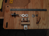
At the top part of the side piece, the drive shaft exits. I needed to provide a bearing support. I drilled a hole just the right
size for the bearing. Then I notched a 3/8" flat washer which allows it to be pinned between two screws without moving to one side
to serve as a thrust washer. Near the bottom of the gantry side, two chain idlers were to be installed. I again drilled holes for
the bearings, but this time on the inside of the gantry. The mounting bolt for the idler gears holds the bearing in place when the
nuts are screwed down. I then added two notched washers on the outside of the gantry. The exterior bearings slide over the protruding
bolt and rest on the washers.
I found a U-bolt mounting strap at the store and cut it in two pieces. I then used it to make an adjuster for the bottom bearings.
By turning the bolts, the adjuster takes out all of the free play. It is then locked down by tightening the bearing mounting bolt. It
works very well.
|
Gantry Construction


|
I created a simple rectangular box to join the two gantry sides. I measured and remeasured(measure twice, cut once!) the distance as
everything needed to be exact to make sure the gantry was true and square and the gantry sides were perfectly vertical. Otherwise
it would have trouble maintaining its accuracy and moving easily. I threaded the holes in the electrical motors and then ran a
threaded rod through them to mark the location of the mounting holes on the motor mount. The rod leaves an impression in the soft
wood. I drilled a horizontal access hole in the mount to allow the coupling to be removed without having to remove the motor
itself. I then installed the motor into the gantry.
Using simple 1/4" rolled steel from the store, I measured and cut two drive shafts and installed them. I used a collar on the shaft at
the gantry bearing to control endplay. I made and fitted the back of the gantry at this time, but left it off for access as other work
needed to be done on the gantry. I drilled holes and affixed the top rail support to the front face of the gantry. I don't have a
pic of the bottom rail support, but you can see it in later pictures. The bolt holes on the bottom rail support are elongated to
allow for some adjustment.
|
Z-Axis gantry and mounting plate


|


|
Creating the mounting plate for the Z-axis was another difficult task. I not only had to locate the mounting bearings to affix it to
the horizontal(y-axis) rails and make it adjustable, I had to do the same thing for the vertical(z-axis) gantry. Plus I had to decide where the
mounting for the Z-axis drive screw would be located. And to finish it off, I also had to locate the mounting bolts to affix the horizontal
drive motor to the mounting plate. This also required a mounting bolt location for a chain idler used in the Y-axis driveline.
I constructed the vertical gantry w/ side rails and fitted it to the mounting plate. I then crafted the Z-axis motor mount and attached
it to the top of the gantry with recessed wood screws. After some finangling, I located the mounting locations for the upper bearing and
for the anti-backlash fitting on the drive screw. I then made the pieces for the installation.
The Y-axis motor was mounted and the real fun began. I probably made more mistakes and adjustments in this area than anywhere else on
the machine. I remade the motor mount, moved the motor to a different height, reworked the idler gear mounting, modified the drive chain
mounts, etc. Finally I got it running smoothly. For the gantry drive chains, I mounted one end securely, threaded it through the drive
gears and then used a turnbuckle at the other end to adjust the tension. The final product with rotor mounting brackets. One of the
brackets broke and I made different brackets that are pictured later. Looks pretty sweet.
Next was installing the drive chains and tensioning. The first picture shows the mounting which is a folded over chain secured with wire.
Tension is held at the other end using a turnbuckle. The chain is fed through the turnbuckle loop and wired in place. The turnbuckle allows the chain to
float a bit in usage(twist) which makes it run a bit smoother. Also in the picture is the stop switch to prevent the machine from hitting the
hard stop when it gets confused. The last pic is of the difficult Y-axis gantry drive system. Spinning motor and gears, wires moving back and
forth and Z-axis wires all in the same location. It took several tries to get everything to where it will work without getting fouled up. Some
more clean-up work needed here.
|
CNC Electronics
|
|
|
|
|
|
|
|
| |